- Inscrit
- 18/11/19
- messages
- 413
- Localisation
- 34920 Le Crès
- Marque
- VW
- Modèle
- Golf
- Date
- 13/11/12
- Cylindrée
- 2
- Km
- 180000
- Type
- Diesel
- Code moteur
- CRBC
- Code boite
- PFL
- Code pont
- 6S
- VIN
- WVWZZZAUZDP015309
- VCDS
- VCDS
Salut,
Ce fil me sert de suivi et sera mis à jour au fur et à mesure, si vous avez des commentaires, n'hésitez pas
Depuis plusieurs mois, je récupère des informations et autres matériel nécessaire à la réalisation du rétrofit de la caméra frontale sur une Golf 7.
Ce rétrofit est sensé pouvoir ajouter plusieurs fonctions à la voiture tels que le lane assist, sign assist, dynamic light assist (si on a les feux directionnels), etc.
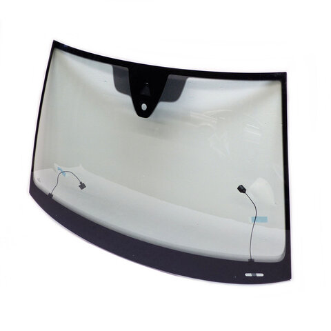
J'ai vu que plusieurs personnes changent leur parebrise pour pouvoir prendre celui qui inclue une zone "blanche" pour la caméra.
Ça me paraissait bien trop contraignant et j'ai cherché une autre solution.
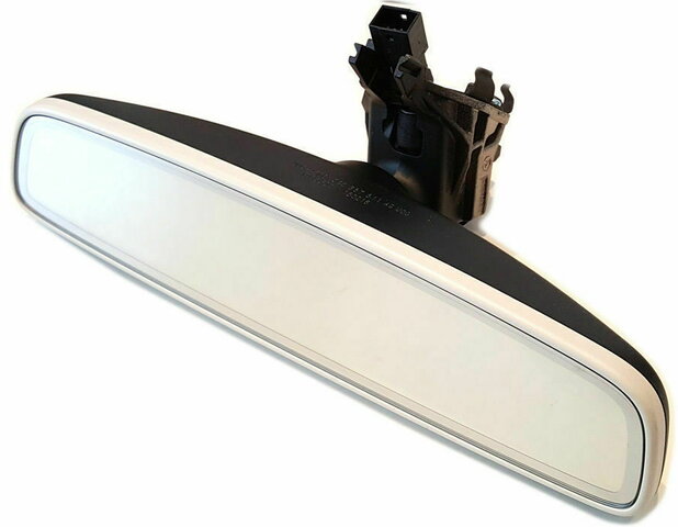
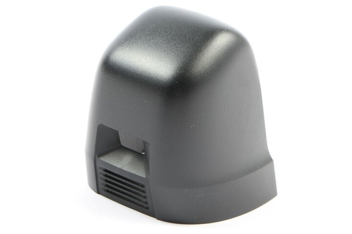
Pour finalement trouver l'astuce d'insérer la caméra dans l'excroissance du rétroviseur.
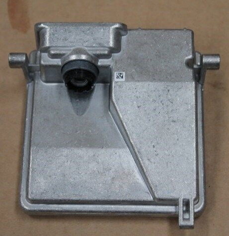
L'installation consistera donc à installer l'objectif de la caméra au niveau du rétroviseur et de fixer le boitier caméra dans le ciel de toit.
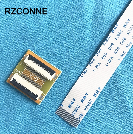
Pour cela, il faut changer le rétroviseur pour un permettant l'installation de l'objectif de la caméra, et relier l'objectif et le boitier avec une extension de nappe.
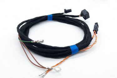
Au fil du temps et des opportunités sur internet, j'ai récupéré :
Pour la partie Caméra
Pour la partie Régulateur de distance (ACC)
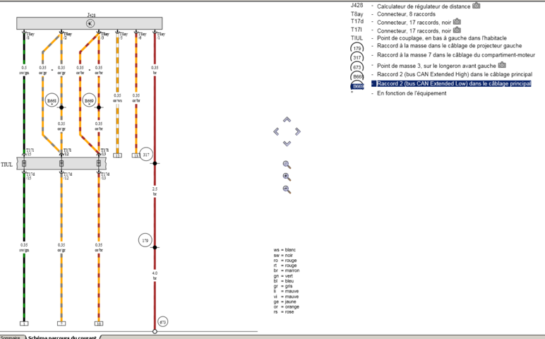
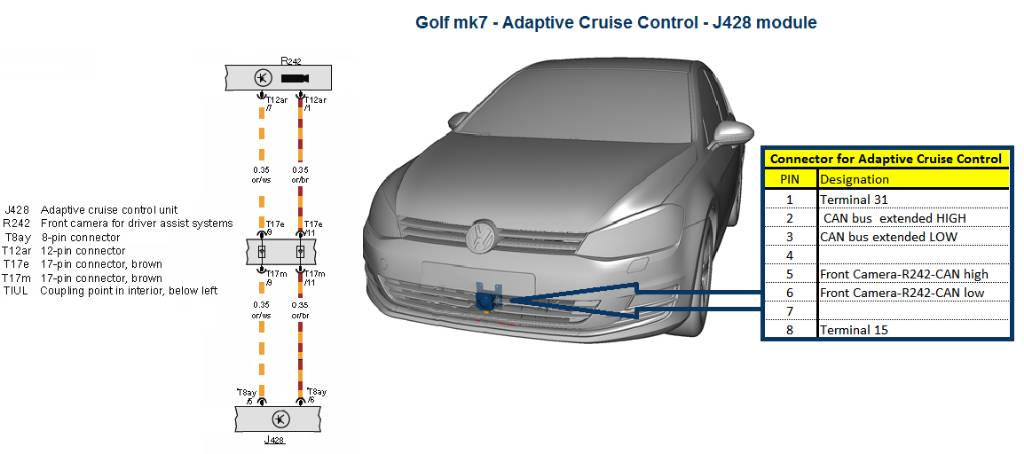
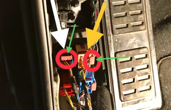
Schéma de branchement :
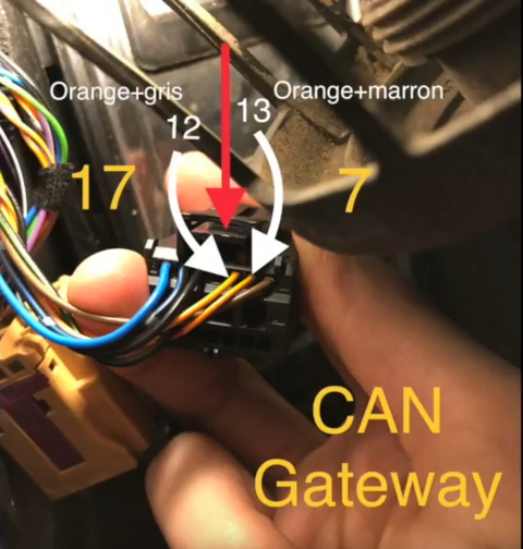
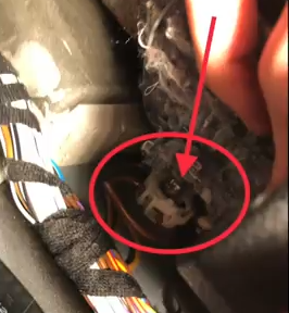
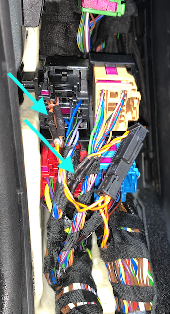 Basically, what you're going to do is pull the two wires that you're pointing to (the Orange/Grey and Orange/Brown wires that are plugged into the 17-pin black connector) and plug those into the "female" ports of the small black connector you're holding in your hand. That black connector is effectively a splitter - takes one wire coming in and splits it two ways: The short ends on the other end of your two-port black connector simply go back into the ports on the 17-pin black connector; the long ends (that big roll of OR/BR and OR/GR CAN twisted wire) go to the ACC camera.
Now, having said all that, I ran into an issue where my metal terminal ends did not fit into the connector - maybe you'll have better luck than I did. After trying numerous times, I ended up cutting the wires and using heat-shrink butt connectors to change the terminal ends from one to the other..
Elle porte le code VAS6430 (à télécharger en pièce jointe).
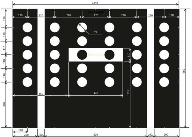
Je pense le faire imprimer sur internet (une 20aine d'€)
Le protocole de calibration :
Activation avec VCDS :
Vidéo Youtube en 3 parties :
Pour enlever la garniture à coté du repose pied :
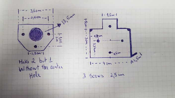
Support de caméra :
Q1 : les tutoriels trouvés montrent l'utilisation de ODIS que je n'ai pas. Mais j'ai VCDS. Du coup, est-il possible de faire toute la manipulation avec VCDS ? Et si oui, quelle est-elle ?
Q2 : Je possède l'ACC. Suis-je obligé de cabler comme indiqué ou est-ce cablé d'origine ?
Q3 : Ou brancher les pins 1, 2, 7 et 8 (pas compris précisément) ?
Notes non triées :
... à continuer
Ce fil me sert de suivi et sera mis à jour au fur et à mesure, si vous avez des commentaires, n'hésitez pas
Depuis plusieurs mois, je récupère des informations et autres matériel nécessaire à la réalisation du rétrofit de la caméra frontale sur une Golf 7.
Ce rétrofit est sensé pouvoir ajouter plusieurs fonctions à la voiture tels que le lane assist, sign assist, dynamic light assist (si on a les feux directionnels), etc.

J'ai vu que plusieurs personnes changent leur parebrise pour pouvoir prendre celui qui inclue une zone "blanche" pour la caméra.
Ça me paraissait bien trop contraignant et j'ai cherché une autre solution.
Pour finalement trouver l'astuce d'insérer la caméra dans l'excroissance du rétroviseur.
L'installation consistera donc à installer l'objectif de la caméra au niveau du rétroviseur et de fixer le boitier caméra dans le ciel de toit.
Pour cela, il faut changer le rétroviseur pour un permettant l'installation de l'objectif de la caméra, et relier l'objectif et le boitier avec une extension de nappe.
Matériel
Au fil du temps et des opportunités sur internet, j'ai récupéré :
Schémas électriques
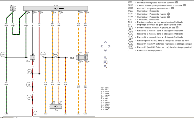
Concernant le raccordement électrique, j'ai les schémas de la voiturePour la partie Caméra


Pour la partie Régulateur de distance (ACC)


Connexion de câblage
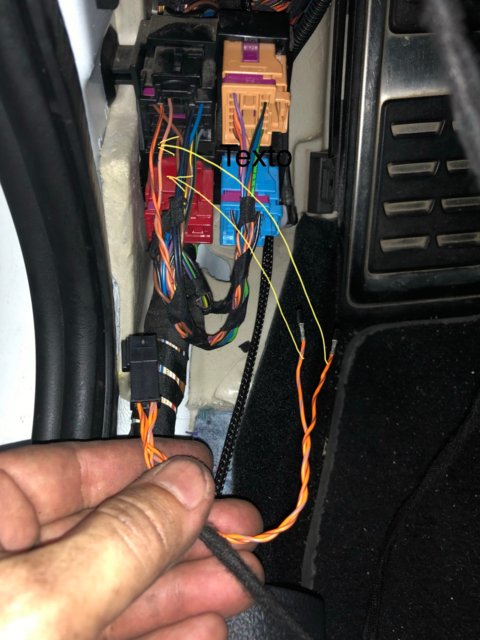
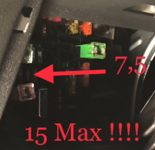
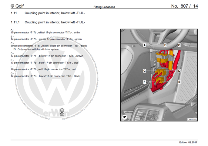
Voici le tableau de connecteur à coté du repose pied.
Schéma de branchement :
 Basically, what you're going to do is pull the two wires that you're pointing to (the Orange/Grey and Orange/Brown wires that are plugged into the 17-pin black connector) and plug those into the "female" ports of the small black connector you're holding in your hand. That black connector is effectively a splitter - takes one wire coming in and splits it two ways: The short ends on the other end of your two-port black connector simply go back into the ports on the 17-pin black connector; the long ends (that big roll of OR/BR and OR/GR CAN twisted wire) go to the ACC camera.
Now, having said all that, I ran into an issue where my metal terminal ends did not fit into the connector - maybe you'll have better luck than I did. After trying numerous times, I ended up cutting the wires and using heat-shrink butt connectors to change the terminal ends from one to the other..
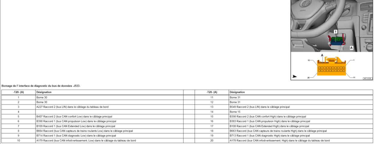
Concernant le branchement sur le CAN extended H & L des pins 2 & 8
Pour se repiquer sur le connecteur J533 (Interface de diag)
Fixation de la caméra

Calibration de la caméra
Pour la caméra, une fois installée, il faudra la calibrer. Pour cela, il faudra imprimer une affiche spéciale contenant la mire de calibration.Elle porte le code VAS6430 (à télécharger en pièce jointe).

Je pense le faire imprimer sur internet (une 20aine d'€)
Le protocole de calibration :
- Horizontalement : l'affiche de calibration doit être placée à 150cm +/- 2cm depuis le milieu des roues. Il faut par ailleurs qu'elle soit parfaitement allignée par rapport aux 2 roues.
- Verticalement : le centre du rectangle blanc contenant les 2 points noirs doit être à la meme hauteur que l'objectif de la caméra (approximativement 120-125cm du sol en fonction des suspensions et des roues)
You must have your car's model software on your A5 camera (for values calcul).
Enter good values for wheel edge housing on Adaptations with security access.
Control camera height calculated by controller with real value.
Adjust values if needed to obtain the good camera height.
Then:
Basic settings -> search target (to recognize it) -> initial online calibration (to calculate camera's angles, which will change as you drive and the car moves) -> static calibration... finished
It took about two minutes... after a couple of days scratching head.
Then you drive on straight's roads and dynamic calibration will be done correctly. Straighter the road is, quicker the calibration will be.
No need to run EAL calibration, it's done for blank cameras.
Documentation
Principale source d'inspiration :
You do not have permission to view link please Connexion or S'inscrire
Activation avec VCDS :
You do not have permission to view link please Connexion or S'inscrire
Vidéo Youtube en 3 parties :
Pour enlever la garniture à coté du repose pied :
Support de caméra :
You do not have permission to view link please Connexion or S'inscrire
Questions ouvertes
Points qu'il me reste à résoudre pour pouvoir me lancer.Q1 : les tutoriels trouvés montrent l'utilisation de ODIS que je n'ai pas. Mais j'ai VCDS. Du coup, est-il possible de faire toute la manipulation avec VCDS ? Et si oui, quelle est-elle ?
Q2 : Je possède l'ACC. Suis-je obligé de cabler comme indiqué ou est-ce cablé d'origine ?
Notes non triées :
The 4 data cables goes as
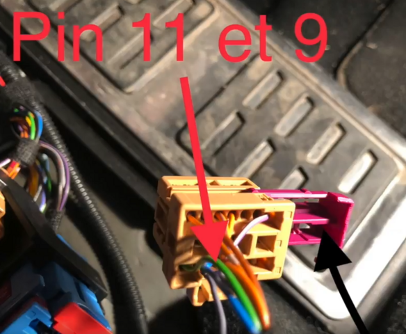
camera pin 1 >> To CanBus 2 Brown Plug pin 11
camera pin 7 >> To CanBus 2 Brown Plug pin 9
(there is no adaptive cruise control for me so i stop there)
camera pin 2 >> To CanBus 1 CAN-LOW
camera pin 8 >> To CanBus 1 CAN HIGH
So for pins 2 and 8 , the Cangateway Red plug is no Go for me ,
So i just need to find the
CAN-LOW
CAN-HIGH
Either to the "black plug" of the previous picture ..
Or i saw that my META System Alarm is using Can H- Can L
Traffic sign Assist:
Controller 5F (Information Electrical)
10 - Adaptations
Select channel: (63) Car_Function_List_BAP_Gen2-traffic_sign_recognition_0x21
Adjust Value to activated
Channel: (151) Car_Function_Adaptations_Gen2-menu_menu_display_road_sign_identification
Adjust Value to activated
Controller A5 (Front / front view camera)
07 - Coding
Byte 1
Bit 0 Enable - "01 traffic sign recognition (FTE) active"
Controller 17 (Instruments)
07 Coding
Byte 5
Bit 2 Enable - "Traffic Sign Recognition installed"
Controller 5F (Information Electr.)
07 - Coding
Byte 24 Bit 6 - tick Traffic Sign Display (VZA) active
Controller A5 (Front / front view camera)
07 - Coding
Byte 16
Bit 4 - tick this box (currently there are no descriptions for A5 longcoding)
Lane Assist: (Not in english but the settings are)
STG 17 (Schalttafel) auswählen
STG Lange Codierung -> Funktion 07
Bye 4
Bit 6 Spurhalteassistent/Lane Assist Active
Bye 11
Bit 1 Spurhalteassistent/Lane Assist Information BAP verbaut Active
STG A5 (Front-/Vorfeldkamera) auswählen
STG Lange Codierung -> Funktion 07
Byte 0
Bit 0 Spurhalteassistent HCA verbaut Active
STG A5 (Front-/Vorfeldkamera) auswählen
Security Access 20103 eingeben
Adaptation
Kanal - HCA_On_State auswählen
Setting via Menu
Kanal - HCA_Warning_intensity auswählen
Setting via Menu
Kanal - BAP_Personalisierung auswählen
Wert auf nicht aktiviert setzen
Kanal - Eingriffszeitpunkt auswählen
Late Setting via menu
Kanal - Personalisierung Spurthalteassistent bei Kl.15 ein auswählen
Last setting
STG 44 (Lenkhilfe) auswählen
Zugriffscode 19249 eingeben
STG Lange Codierung -> Funktion 07
Bye 0
Bit 4 Spurhalteassistent HCA verbaut aktivieren
STG 5F (Informationselektronik) auswählen
STG Anpassung -> Funktion 10
Kanal - (49)-Fahrzeug Funktionsliste BAP-LDW_HCA_0x19 auswählen
Wert auf Aktiviert setzen
Kanal - (21)-Fahrzeug Menü Bedienung-menu_display_Lane_Departure_Warning auswählen
Wert auf Aktiviert setzen
Kanal - (23)-Fahrzeug Menü Bedienung_menu_display_Lane_Departure_Warning_over_threshold_high auswählen
Wert auf Aktiviert setzen
High Beam Assist
09 Cental Electrics
Security access 31347
Adapation
Assistance light functions Menuesteuerung Fernlichtassistent
Change to Present (Enables setting on menu)
Then go to long coding of 09 Central Electrics
Byte 2 Bit 0 to 1
The byte should change from 0A to 0B for 6mt, Or 1A to 1B on DSG (I Had to mess a bit with these settings as I Have Bi xenon Replicas)
A5
Long coding
For 5Q0980653G Set byte 2 to 01 light assist AFS: High beam assist
For 3Q0980654G
Set byte 21 to 20 light assist AFS: High beam assist
Then go to car - setup - light - And enable light assist.
Set your light switch to Auto and flick the lever just as you would turn high beams on and it will show the HBA Icon on the dash.
... à continuer
Pièces jointes
-
302.4 KB Affichages: 24
Dernière édition:

